The future of flying antennas
20 Aug 2020
Taken from the 2020 Physics World Instruments & Vacuum Briefing. Members of the Institute of Physics can enjoy the full issue via the Physics World app.
Designing equipment that meets stringent size and mass restrictions for use on aircraft brings extra challenges for instrument developers, as Tamara Clelford explains

Antennas are used for a huge range of applications, from mobile phones and “smart” WiFi-connected appliances to GPS and systems that track aircraft and help pilots land safely. These systems usually have a few things in common: the antenna itself, which manipulates electromagnetic radiation in the radio and microwave parts of the spectrum; a receiver (if the system receives signals); and a transmitter (if the system transmits). Over the years, several distinct types of antennas have come into common use, with designs, frequencies and operating power levels that depend strongly on their purpose. Examples include patch antennas in mobile phones, wire antennas in household radio receivers, and reflector antennas for satellite TV.
Within this antenna “zoo”, the antennas attached to flying structures are unique in several respects. Stringent mass and size restrictions make their design more complicated, and they must be able to cope with several challenges over and above meeting basic radio-frequency (RF) requirements. These problems are most acute for radar systems, which require a highly directional beam that can be scanned in different directions.
Purpose and options
A radar antenna at the front of an aeroplane, helicopter, drone, missile or other flying structure is there to scan its surroundings, identify objects (such as terrain, buildings, cars, ships and aeroplanes), and then either avoid them or track them. To accomplish this, the beam of the antenna needs to be moved around in a controlled pattern such as a raster scan. The results of this scan and subsequent computer processing will produce a picture of the area around where the antenna is looking.
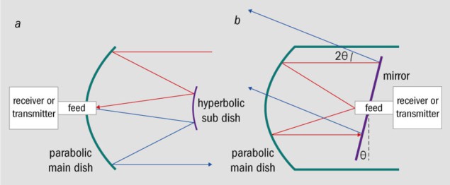
There are three basic ways of making the antenna beam move. From an RF design perspective, the simplest approach is to use a reflector antenna that moves around in its entirety. These types of antenna are normally of a Cassegrain design (figure 1a) and are often seen at airports, where radar systems employ large, spinning reflector dishes, and on radio telescopes where the dish moves to track the object as it moves across the sky. In both cases, the antennas are made from conductive materials that strongly reflect RF signals, and their collecting area focuses this reflected RF energy onto a feed element that routes the signal (via a transmission line) to the receiver for further processing.
The major problem with physically scanning the entire antenna in airborne applications is that the available space at the front of a flying object is often small. Allowing extra room for physical movement means the antenna itself must be made smaller – a compromise that leads to worse resolution and lower sensitivity relative to a design that uses all the available space. However, if the flying structure is large – say, an aircraft – then this can be an acceptable solution. Many specimens of mechanically scanned airborne antennas exist, including the Foxhunter radar on the Royal Air Force’s (now-retired) Tornado F3 jet. 1 Design options Schematic ray tracing diagrams for two types of RF reflector antenna. (a) In Cassegrain antennas like this one, the receive and transmit hardware can be hidden behind the main dish so that they do not interfere with the beam. (b) A version of the twist reflector antenna design that allows the twist plate mirror to be moved to scan the beam.
 1 Design options Schematic ray tracing diagrams for two types of RF reflector antenna. (a) In Cassegrain antennas like this one, the receive and transmit hardware can be hidden behind the main dish so that they do not interfere with the beam. (b) A version of the twist reflector antenna design that allows the twist plate mirror to be moved to scan the beam.
The second way of making an antenna beam move is to move only part of the antenna, such as its primary reflector. However, this generally produces a degraded antenna beam that performs worse when it is scanned significantly away from straight ahead. Again, this compromise is often acceptable, and some designs have been developed to minimize the degradation in performance. The twist reflector design, for example, introduces a moving planar reflector to the basic reflector antenna, enabling the beam to be scanned without defocussing the system (figure 1b). This makes it possible to maximize the available aperture for the RF collecting area, while scanning the beam with the mechanical moving plate. Such designs do exhibit some degradation of antenna performance at high angles, but for the most part they work well.
A variant of this solution is to use a different type of antenna known as a flat-plate array. Antennas of this type contain small radiating elements such as a slotted waveguide, patch or helical wire antennas. These elements are connected to a common transmitter and receiver, producing a coherent beam that can be scanned by moving the plate with motors and push rods. This method uses most of the available aperture of the antenna as a collecting area, while losing only a small amount to allow for the beam movement, and without introducing any distortion of the pattern at high scan angles.
Electronic alternatives
Flat-plate arrays and twist-reflector-based designs are both viable solutions on flying platforms, with many successful implementations. However, mechanically scanning all or part of an antenna is not the only way to steer a beam. The third way of scanning an antenna beam is to control the beam direction purely electronically, without any moving parts.
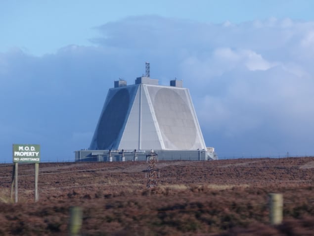
One such electronically steered antenna is known as a phased array. Like the flat-plate antenna, phased arrays incorporate multiple small elements that are connected to the same transmit-and-receive hardware and combine to produce a coherent beam. Phased arrays have been in use since the 1960s, but a variation of this design known as an Active Electronically Steered Antenna (AESA) was developed more recently. In an AESA, each element in the array has its own transmitter and receiver. This set-up enables the elements to be controlled independently, while software is then used to combine the signals from all the elements to create a single beam. Radome evolution Golf-ball-shaped radar domes, or radomes, were a well-known feature and tourist attraction in the UK. Originally built to cover mechanically scanning antennas, these “golf balls” have now been replaced by AESA antennas housed on structures like the one shown here at RAF Fylingdales in the North York Moors. (CC BY-SA Cherubino)
 Radome evolution Golf-ball-shaped radar domes, or radomes, were a well-known feature and tourist attraction in the UK. Originally built to cover mechanically scanning antennas, these “golf balls” have now been replaced by AESA antennas housed on structures like the one shown here at RAF Fylingdales in the North York Moors. (CC BY-SA Cherubino)
From a tracking radar perspective, the interesting thing about the AESA design is that having individual control of each element makes it possible to produce multiple beams in different directions and at different frequencies at the same time. These multiple beams and frequencies are especially beneficial for flying antennas, as they make it more difficult for external sources to interfere with the signal.
The main drawback of electronically steered antennas is that they have a maximum scan range. While it is possible to electronically scan an antenna beam 60° from perpendicular, the beam inevitably degrades as scan angle is increased, and getting to 90° of scan (let alone 180°) is not possible. Practical systems that need wider scanning therefore need some way of addressing this.
Design iterations
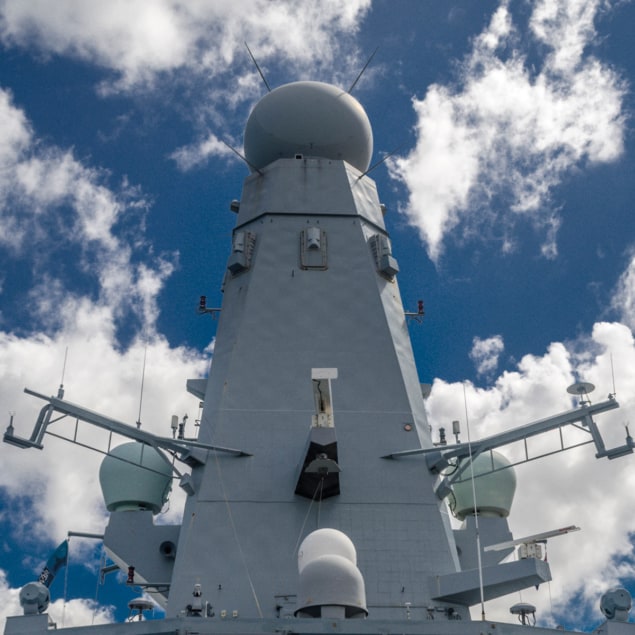
The first examples of AESAs were ground-based. In these applications, the space behind the antennas is not at a premium, so there is room to house (and cool) all the AESA’s connecting electronics, transmitter and receivers. An early naval example is the large Sampson AESA radar used on the Royal Navy’s Type 45 class destroyer, which tracks targets and communicates this information to the guided missiles onboard. Because these systems typically aim to survey the entire sky, it is crucial that they overcome the limitation on maximum scan angle. Some ground and naval based AESAs do this by having multiple faces to the antenna (often in a triangular formation) and/or mounting the antenna on a revolving gimble to produce 360° of coverage.
For airborne applications, the limitation on scan angle may also need to be overcome via mechanical movement or multiple arrays. One airborne example can be found in the KLJ-7A AESA radar to be installed on the JF-17 fighter plane, which was developed by the Nanjing Research Institute of Electronics Technology in China. This aircraft uses two types of AESA: a single moving flat-plate AESA and a variant with one front AESA antenna and two side AESA arrays.
When designing a radar system, the trade-offs between electronic and mechanical scanning are complicated. It is certainly not the case that electronically steered arrays have replaced mechanical ones entirely. While mechanically scanned antennas have moving parts that can break, and that need to be maintained and calibrated, the antennas themselves are less complex and cheaper to manufacture than AESAs. The data they produce are also more easily processed, which has kept them in circulation for a long time. All at sea The Sampson radar system installed on vessels such as the HMS Daring is an example of a naval AESA. (CC BY-SA Hpeterswald)
 All at sea The Sampson radar system installed on vessels such as the HMS Daring is an example of a naval AESA. (CC BY-SA Hpeterswald)
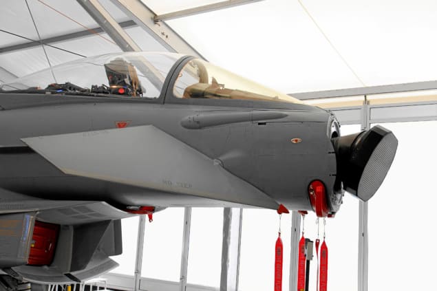
AESAs do address some of the issues with a traditional scanned antenna. They allow the use of the full aperture, thereby maximizing the available space, and enable the beam to be scanned to a reasonably wide range of angles. However, for flying antennas, space is especially limited, and restrictions on mass make it more difficult to design AESAs that fit in these smaller spaces. In a flying object the size of an aircraft, an AESA is a viable and indeed a popular choice today, with AESAs used in combination with mechanical solutions on Rafale, Seaspray and Wedgetail aircraft, to name but a few. However, in smaller craft such as missiles, drones or other unmanned aerial vehicles, the space, mass and cooling difficulties of AESAs are harder to mitigate. Companies have been working on this problem for many years, but barriers remain, and there have been some unfortunate errors along the way. The first attempt to use an AESA on a missile (the AAM-4B) resulted in the missile being too large to be carried in the weapons bay of the aeroplane.
In the longer term, moving towards a purely AESA solution is clearly desirable for small flying objects. A purely electronic antenna will remove the problems caused by mechanically scanning and allow the system to look in more than one direction at a time. It may even be possible to track more than one object at a time, which would greatly improve performance and usability. This option is currently being investigated by various companies, but it brings new challenges to the table.
Because the beam steering of such an antenna will need to be at least 180°, flat AESAs can no longer be used, but changing the profile of the AESA from 2D to 3D will make signal processing much more difficult. A 3D AESA will also further restrict the space available for the electronics behind the antenna. This brings major challenges for the design and manufacture of the antenna, both to fit everything in and to allow sufficient cooling. Two developments that may help address these problems are progress in electronic miniaturization and the emergence of new substrates for solid-state hardware. Rapid prototyping technologies may also make it possible to manufacture structures that cannot be made with traditional techniques. Perhaps the area where there is most room for novel approaches, however, is in understanding how the RF signals interact in a 3D structure and the signal processing required to extract meaningful measurements. Despite the outwardly slow pace of change in the aerospace industry (due to safety considerations and legacy systems), there are plenty of interesting problems within it for instrument designers to get stuck into.
Tamara Clelford is a physicist and founder of the RF engineering and data science consultancy Swamphen Enterprises, e-mail tamara@swamphen.co.uk
from physicsworld.com 23/8/2020
Δεν υπάρχουν σχόλια:
Δημοσίευση σχολίου